Crossovers overview - Essential Components and Benefits for Audio Systems
This Crossovers overview explains how LF/HF filters, Zobel networks, and notch filters protect drivers and optimize frequency response for high-fidelity sound.
The Essential Role and Benefits of Crossovers in Audio Systems
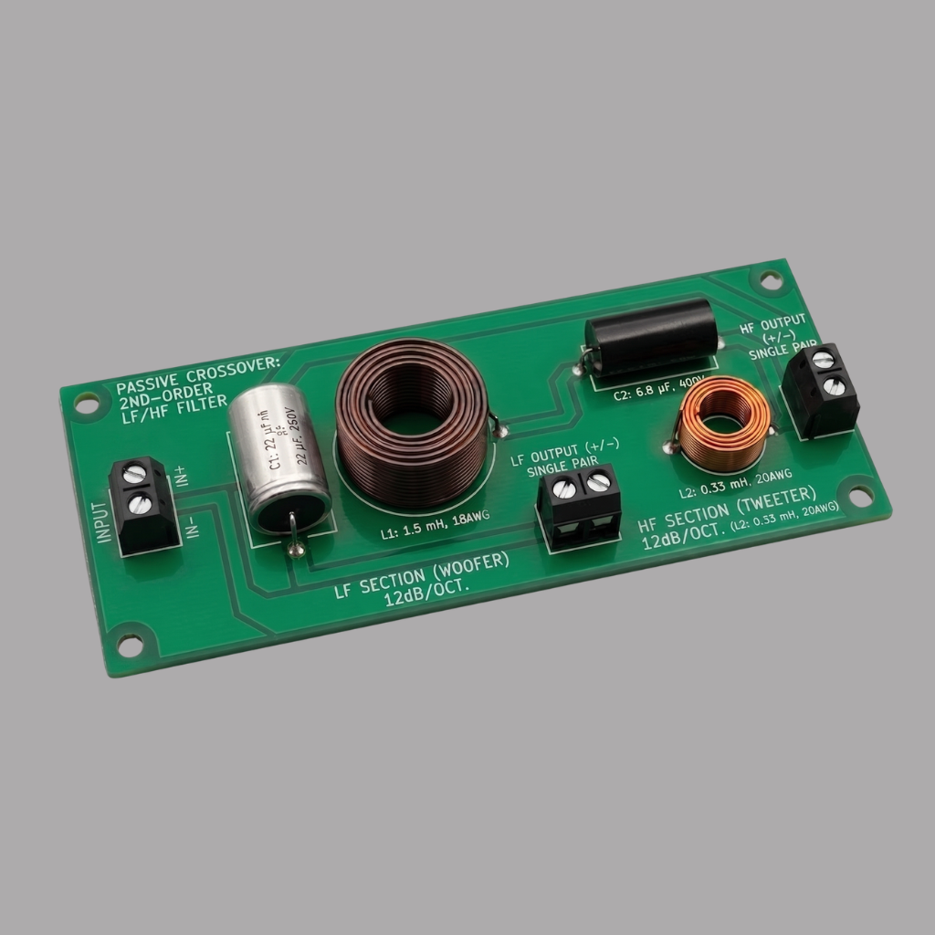
In the architecture of a loudspeaker, the crossover functions as the system's brain, orchestrating the complex distribution of electrical signals. Its primary objective is to divide the incoming full-range audio signal into specific frequency bands, ensuring that each transducer - whether a woofer, midrange, or tweeter - receives only the frequencies it was designed to reproduce efficiently.
This division provides several critical performance benefits. By filtering out frequencies outside a driver's optimal range, the crossover significantly improves power handling; for instance, it prevents high-energy low-frequency signals from reaching and damaging sensitive high-frequency tweeters. Furthermore, it minimizes distortion by keeping drivers within their linear excursion limits and away from resonance-prone regions or cone breakup modes. Ultimately, the crossover is responsible for optimizing the overall frequency response and phase alignment of the system. For the DIY builder and audio engineer using Speaker Box Lite, understanding these networks is the first step in achieving a seamless transition between drivers and a balanced, professional sound signature.
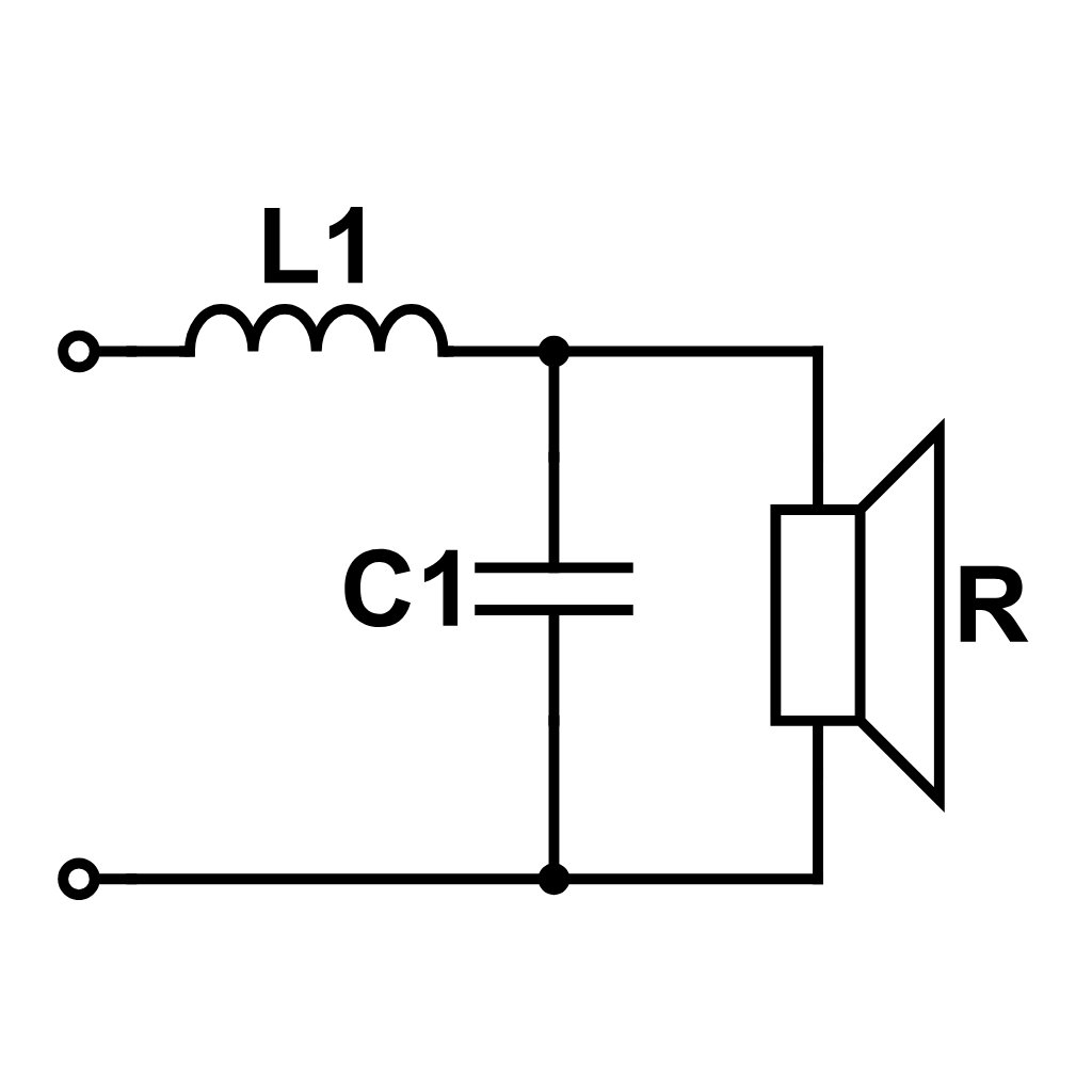
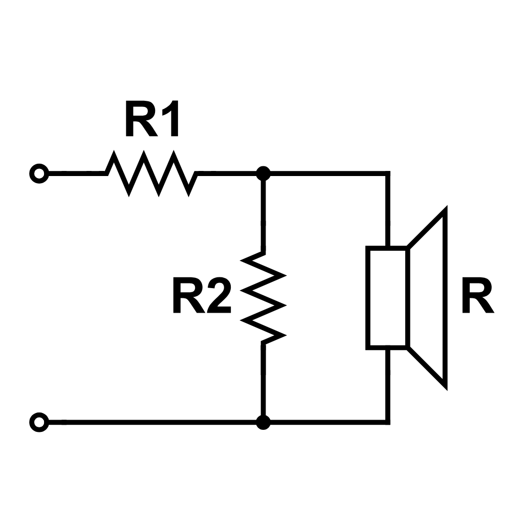
Basic two-way LF-HF crossover network layout
Main Components - Fundamental Frequency Division
At the heart of every crossover network lie two fundamental building blocks: the low-pass and high-pass filters. These primary circuits are responsible for establishing the "crossover point" - the specific frequency where the signal is divided and handed off from one driver to another. This transition ensures that each component operates within its most linear range while maintaining a cohesive overall sound. By precisely defining these frequency boundaries, designers can prevent drivers from struggling with frequencies they cannot efficiently reproduce, laying the essential groundwork for a balanced and reliable loudspeaker system.
The low-pass (LF) filter is a critical component designed to steer the signal's energy, allowing low frequencies to reach the woofer while progressively rolling off higher frequencies. By attenuating the high-frequency content that the woofer is physically unequipped to handle, the filter prevents "cone breakup" - a phenomenon where the driver diaphragm loses structural rigidity and produces harsh, non-linear distortion. Additionally, this filtering reduces intermodulation distortion (IMD), ensuring the woofer remains within its optimal operating range without wasting energy on frequencies it cannot accurately reproduce.
Speaker Box Lite offers extensive flexibility for designing these circuits, supporting filter slopes from the 1st order through the 6th order. Engineers can precisely model their system using various filter alignments, including Butterworth for its maximally flat passband response or Linkwitz-Riley, which is highly valued for its superior phase alignment and flat summation at the crossover point.
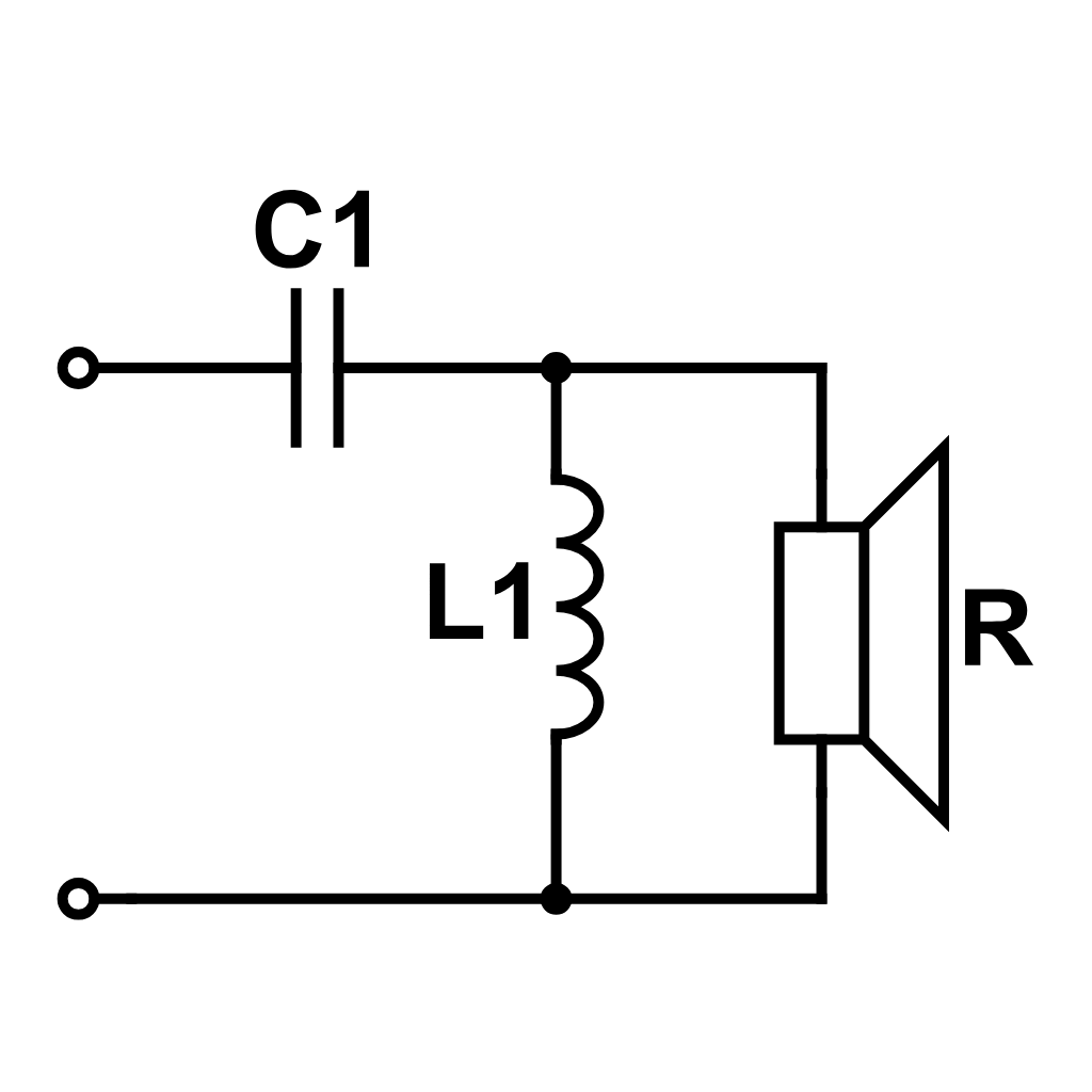
A high-pass (HF) filter serves as the essential guardian for the most delicate component in your system - the tweeter. Its primary function is to block low-frequency energy that can be catastrophic to small drivers. Because tweeters feature lightweight voice coils and extremely limited mechanical excursion, exposure to long-wavelength bass signals causes immediate distortion and potential physical destruction. Without a proper HF filter, the tweeter would attempt to reproduce frequencies it cannot handle, leading to thermal failure or mechanical "bottoming out."
Within Speaker Box Lite, users can configure high-pass filters ranging from gentle 1st-order slopes (6dB/octave) to steep 6th-order slopes (36dB/octave). Higher-order filters provide superior protection by rapidly attenuating out-of-band signals, which is vital for maintaining high power handling and sonic clarity. Selecting the right slope ensures the tweeter remains within its linear operating range, free from the stress of low-end energy.
Band-Pass Filters - Implementing Midrange and Midbass Drivers
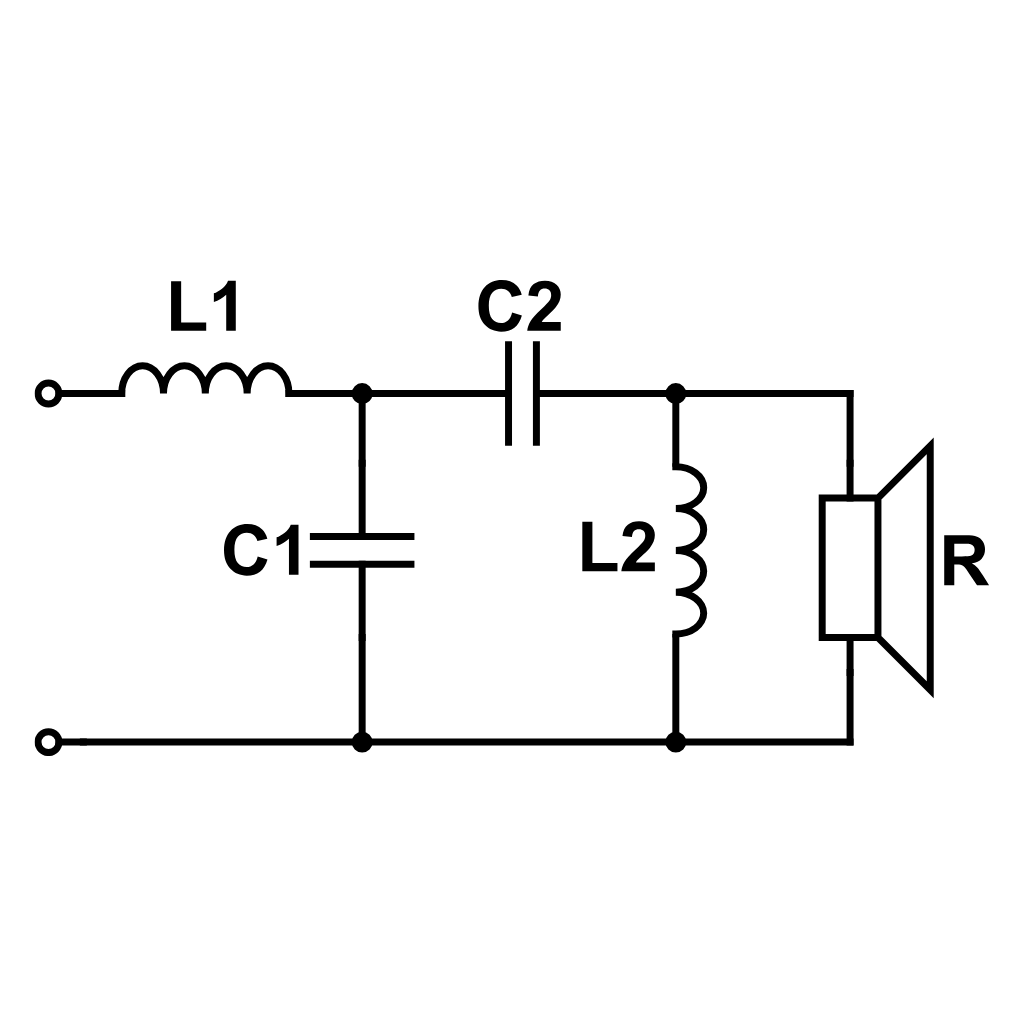
In complex 3-way or 4-way loudspeaker designs, certain drivers are optimized to handle only a specific portion of the frequency spectrum. This is where the band-pass filter becomes indispensable. By "sandwiching" a high-pass filter and a low-pass filter together, you create a dedicated frequency window that isolates the operational range of midrange or midbass units.
The high-pass portion of the filter removes deep bass energy that could cause over-excursion, while the low-pass portion rolls off high frequencies where the driver might exhibit cone breakup or poor off-axis dispersion. In Speaker Box Lite, designing a band-pass filter allows you to define these crossover points with precision. This ensures the midrange unit operates within its most linear region, effectively reducing intermodulation distortion. This "windowing" technique is the key to achieving a balanced, natural sound in multi-driver systems, providing a smooth transition between the powerful woofer and the delicate tweeter.
Helper Circuits - Precision Tuning and Driver Correction
While standard filters manage frequency division, basic crossover math often assumes a constant resistive load. In reality, loudspeaker drivers are complex transducers with inductive properties and mechanical resonances. These real-world behaviors can cause unpredictable filter slopes or harsh sonic artifacts. To address this, audio engineers utilize helper circuits - specialized corrective networks designed to linearize the driver's behavior. These components go beyond simple signal splitting to force the driver to act as a predictable load. By compensating for impedance rises or taming narrow peaks, these circuits ensure the primary crossover operates exactly as intended.
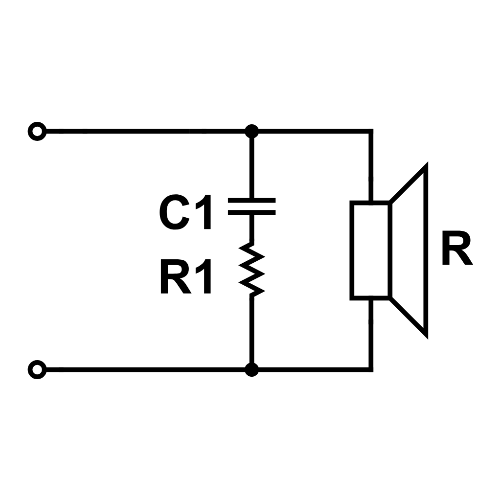
The Zobel Network - Impedance Compensation
Zobel network circuit schematic for driver impedance compensation
A loudspeaker voice coil is inherently inductive, meaning its impedance rises significantly as the signal frequency increases. This behavior is problematic because standard crossover filters are designed to work against a constant resistive load. If the impedance fluctuates, the filter's turnover frequency and slope will deviate from the intended design. To fix this, engineers use a Zobel network - a resistor and capacitor wired in series and connected in parallel with the driver. This circuit counteracts the rising inductance to flatten the impedance curve, ensuring the crossover behaves predictably across the entire frequency range.
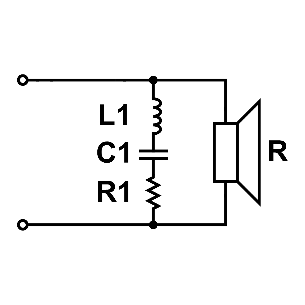
Series Notch Filters - Taming Narrow Resonance Peaks
Series notch filter circuit schematic for narrow-band resonance peak suppression
A series notch filter is a precision tool used to suppress specific narrow-band frequency peaks, often caused by driver cone break-up or mechanical ringing. By arranging an inductor, capacitor, and resistor in a series configuration and placing them in parallel with the driver, you create a circuit that targets a precise frequency range. The specific values of the inductor and capacitor determine the center frequency of the notch, while the resistor controls the attenuation depth. This configuration effectively shunts unwanted energy, eliminating harsh resonances to produce a smoother frequency response and a more natural sound.
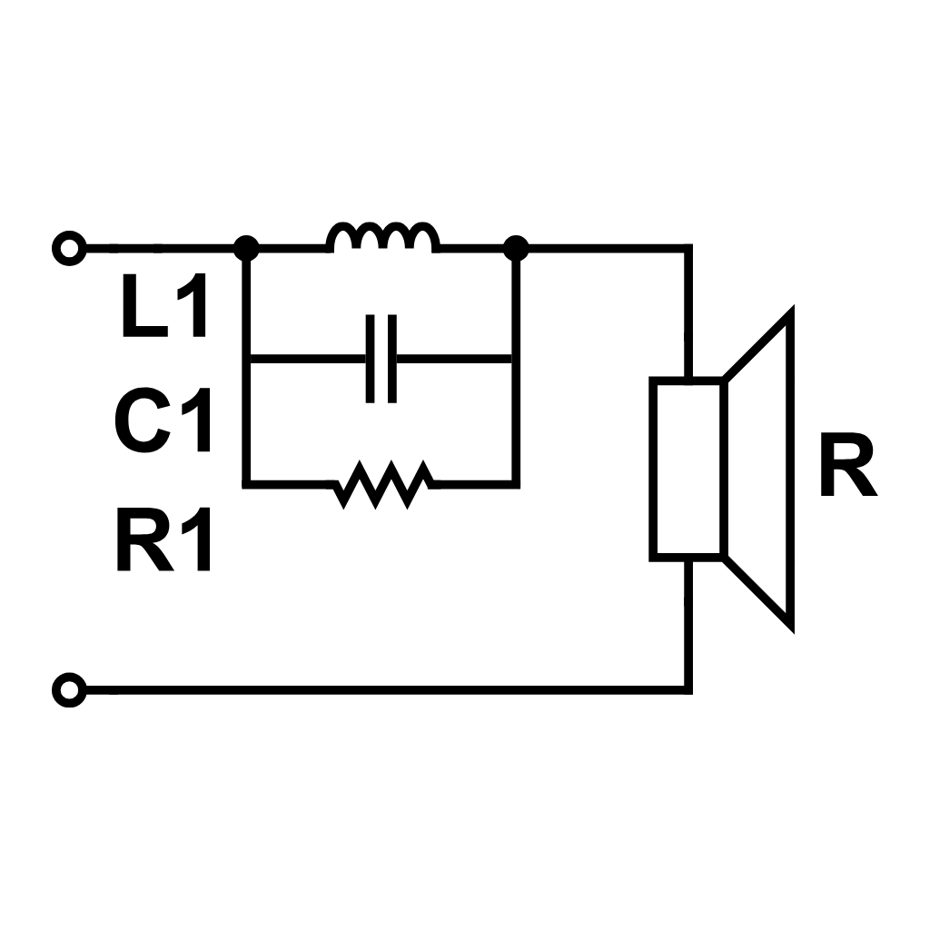
A parallel notch filter targets the mechanical resonance frequency (Fs) of a driver. At this frequency, impedance typically spikes, which can disrupt crossover slopes and cause audible ringing. This circuit - consisting of an inductor, capacitor, and resistor - is wired in parallel with the driver to flatten that peak. It is especially critical for tweeters when the crossover point is set near Fs. By smoothing the impedance curve, the filter ensures the driver stays within its linear operating range, preventing distortion and protecting the component from mechanical stress during high-output playback.
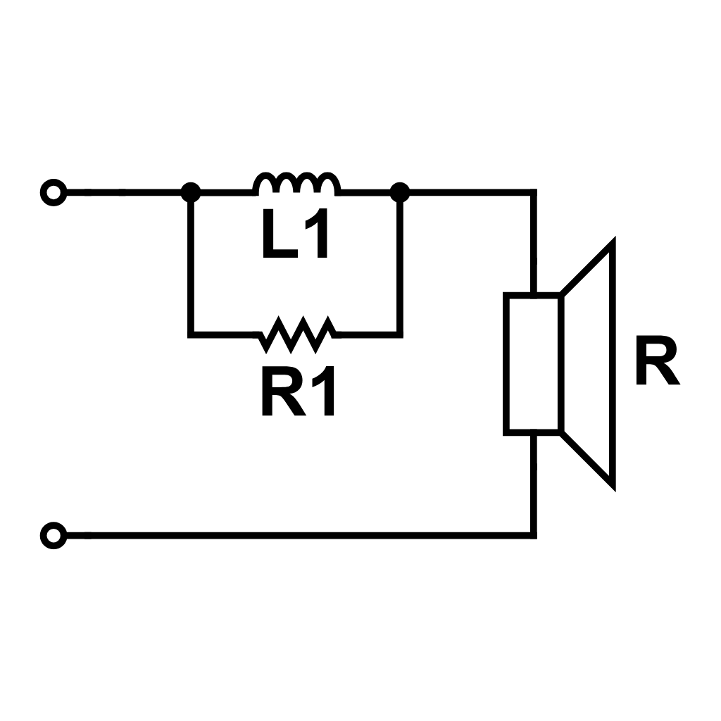
Contour Circuits RL/RC for Response Shaping
RL contour circuit schematic for frequency response shaping and baffle step compensation
Contour circuits - including RL and RC networks - serve as the primary tool for "voicing" a speaker. Unlike notch filters that target narrow peaks, these circuits shape broad frequency ranges to balance the overall tonal response. A common application is Baffle Step Compensation (BSC), where an RL circuit is used to counteract the loss of low-frequency energy caused by the physical dimensions of the cabinet. This restores the bottom end, preventing a thin or "lean" sound. Additionally, contour circuits can tame a "shouty" or bright midrange, ensuring a smooth, musical transition between drivers.
L-Pad attenuators are critical when a tweeter's sensitivity exceeds that of the woofer, a common scenario in high-fidelity designs. Without attenuation, the high-frequency output would overpower the system, ruining the tonal balance. Unlike a simple series resistor - which alters the driver's impedance and shifts the crossover point - an L-Pad utilizes a two-resistor configuration. This design reduces the signal level reaching the tweeter while maintaining a constant impedance load for the crossover filter. This ensures the crossover frequency remains stable while bringing the driver levels into perfect sonic alignment.
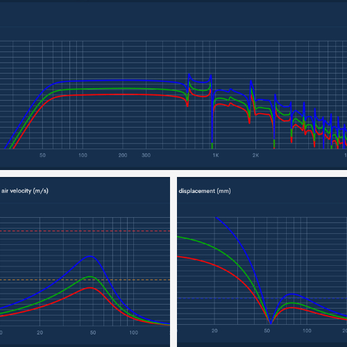
Simulating Filter Performance in Speaker Box Lite
Speaker Box Lite streamlines the crossover design process by allowing virtual prototyping. Start by inputting your driver’s Thiele-Small parameters to establish an accurate baseline. Within the crossover module, you can select specific filter types - including standard LF/HF networks or corrective circuits like the Zobel network. The app generates real-time visualizations of the resulting transfer function and impedance curves. By adjusting component values digitally, you can refine the frequency response and ensure stability before purchasing hardware. This predictive modeling saves time and resources, leading to a more polished, professional audio system.
Conclusion - Achieving Sonic Balance
Achieving true sonic balance requires more than just basic frequency division. While LF and HF filters establish the foundational crossover points, helper circuits - such as Zobel networks, notch filters, and L-pads - provide the necessary refinement to reach high-fidelity standards. These components work in harmony to stabilize impedance and smooth out response irregularities. To ensure your design translates perfectly to the physical world, Speaker Box Lite offers an essential platform for accurate prototyping and design validation. By simulating these complex filter combinations digitally, you can achieve a professional, balanced output while avoiding the costly trial-and-error of manual construction.
Can you explain the height, width, and length of the port?
Can you please explain the height, width, and length of the port? I have changed the height of the port to different numbers but the 3d rendering does not show any changes. I don't understand. When I go to view the parts, none of the dimension change. What part of the port does height and width signify?