Designing a Small Sealed Bookshelf Box for Your Computer Setup
Follow along as we design a sealed (closed) bookshelf speaker enclosure for a computer setup using Speaker Box Lite. We’ll select the driver, simulate the volume, shape the enclosure, adjust the dimensions, mount the speaker, and prepare the final blueprint for cutting and assembly.
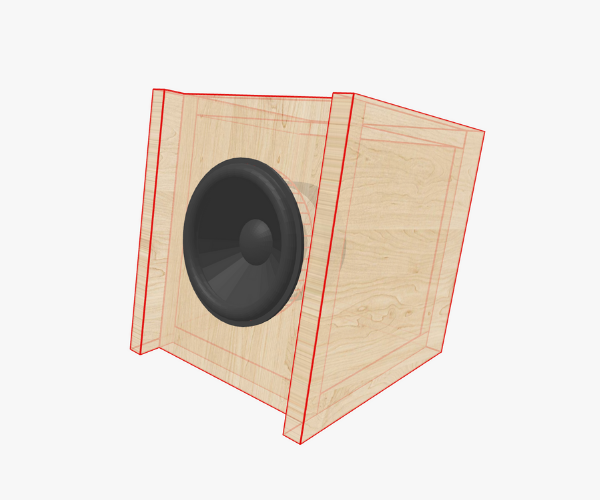
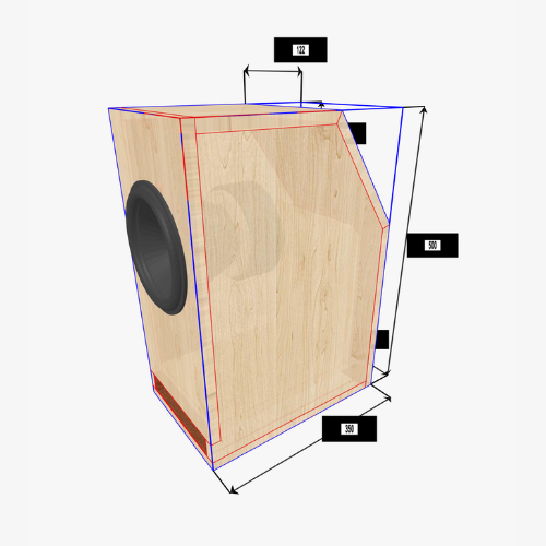
At the very beginning, let’s clarify our goal: in this guide we want to achieve the same result as shown in the screenshot at the top of the article. Every step described here - from choosing the driver to shaping the box and refining its look - is oriented toward recreating that exact example. Of course, you are free to adapt the process to your own taste and setup.
Image demonstrates the result we want to achieve.
Why Start with a Sealed Box?
When building your own speaker enclosure, the sealed (or closed) box is one of the most approachable and rewarding designs. Unlike ported or band-pass enclosures, a sealed box doesn’t rely on tuned vents, ducts, or resonators. Instead, it provides a controlled acoustic suspension for the speaker driver, creating tight, accurate bass and smooth midrange response.
For small setups like a desktop or computer speaker system, this approach shines. You don’t always want booming low end that rattles the walls—you want clarity, detail, and controlled output that sits comfortably at close listening distances. That’s where a sealed bookshelf enclosure comes in. It’s compact, precise, and can be shaped to fit the exact space you have available.
Choosing the Right Speaker Driver
Every box design starts with the driver. For our project, I’ll use the Dayton Audio TCP115-8, a 4-inch midbass woofer with parameters that make it an excellent candidate for a small sealed box.
In Speaker Box Lite, you can either select this driver directly from the built-in database (which includes thousands of drivers from different brands) or enter the manufacturer’s parameters from the datasheet. Once the driver is set, the software immediately calculates possible enclosures based on its Thiele-Small parameters.
This is where the design becomes both science and art.
Finding the Right Box Volume
On the Enclosure tab, you’ll see several starting options for calculating the internal volume of a sealed box:
Max flat amplitude Butterworth-B2
Max flat delay Bessel-BL2
Critically-damped
Chebyshev C2
Chebyshev C2 max power
Each of these methods produces a different target volume and frequency response curve. (If you’re curious about the deeper theory behind them, you can read more in this article)
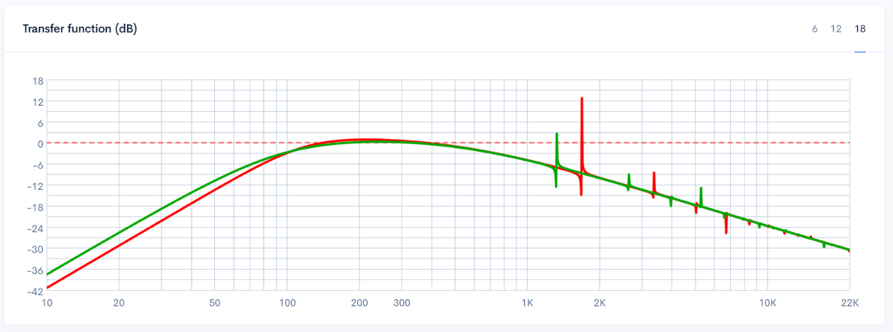
Image shows the result of Max Flat Amplitude Butterworth (Red) and Max Flat Delay Bessel (Green).
For this experiment, I tried both Max flat amplitude Butterworth-B2 and Max flat delay Bessel-BL2. The first gave me a result of about 1.08 liters (shown in red on the response graph), while the second suggested 2.23 liters (green curve).
But here’s the key: you are not forced to pick one of these recommendations and stop there. These are starting points, not absolute rules. Speaker Box Lite lets you overlay multiple plots so you can visually compare the results. Personally, I liked the green curve more because it delivered higher output at lower frequencies. However, the box size became larger than I could reasonably fit into my setup. That’s why I decided to experiment further with the box volume.
I decided to go with a middle ground: 1.7 liters (orange line). It’s a compromise between size and performance. The response curve is slightly lower than the 2.23-liter design, but I save half a liter of space - critical for fitting the box comfortably into my computer desk area.
This step illustrates a valuable principle in enclosure design: you balance theoretical “perfection” with practical needs and personal taste.
Moving to the 3D Box Design
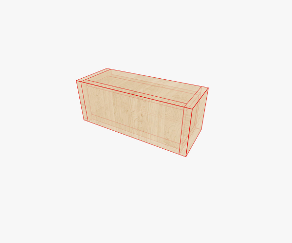
Once the internal volume is chosen, it’s time to bring the box to life. Switching to the 3D Box tab in Speaker Box Lite, you’re greeted with a default rectangular box.
Box with default width, height, and length.
At first glance, it’s just a simple block - but this is where creativity enters. The software allows you to change the foundation shape of the box, essentially redefining how the enclosure is extruded in 3D space.
For my desktop speaker, I wanted the box to angle slightly toward my face. That way, the driver points directly at my ears instead of firing straight ahead or upward. To achieve this, I selected the One-Side Trapezoid foundation.
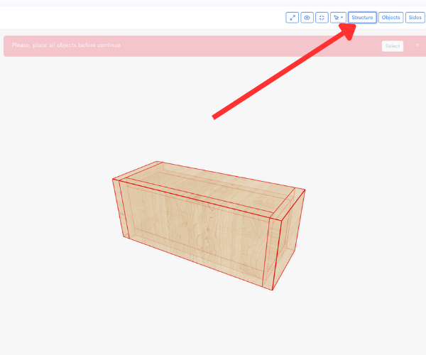
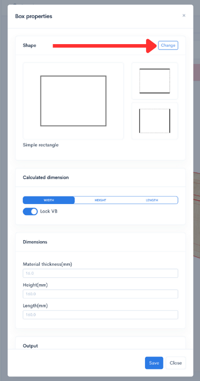
Steps to open the Box Properties window.
You can access this option in the Structure screen under box properties. There’s a button to change the foundation type - once you press it, a menu appears where you select the trapezoid option. Immediately, the box takes on a slanted form, ready to be tailored further.
Steps to change the box’s foundation and material thickness.
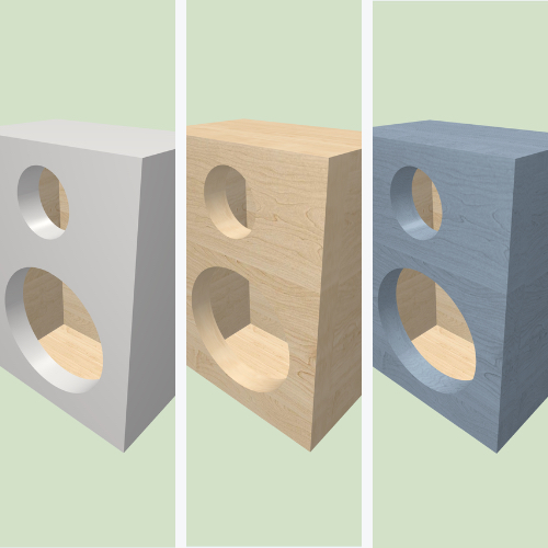
On the same screen, you can also choose the material thickness. For this build, I opted for 12 mm plywood. It’s sturdy enough for a small speaker, lightweight, and easy to work with. With these settings locked in, I saved the changes and returned to the main design view.
Adjusting the Box Dimensions
Now comes the part where the box transforms from theory into a piece of furniture-like design.
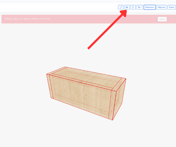
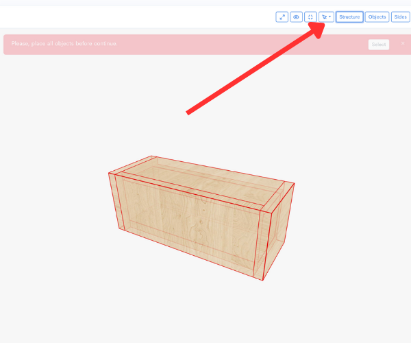
Steps to enable the Box Bounds option.
Speaker Box Lite offers a handy Box bounds mode, which overlays the box with dimension labels. By enabling it, you can click directly on the height, width, or length values to modify them on the fly.
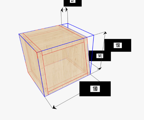
For my project, I wanted something compact but proportionate. I settled on:
Height: 150 mm
Length (depth): 180 mm
The width adjusts automatically to preserve the internal volume of 1.7 liters. This is one of the conveniences of working with software instead of a calculator - you tweak, and the program maintains balance.
Creating the Inclined Front
At this stage, the trapezoid shape was present, but I wanted the entire box to tilt - not just the front face. To do this, I redefined the bottom face of the trapezoid as the true base.
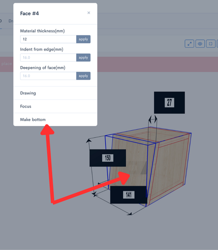
Steps to change the box orientation.
The process is straightforward: click on the desired face, open the menu, and select “Make bottom.” The box reorients itself accordingly. Now the enclosure sits naturally inclined, with the driver pointing upward and forward, directly at the listener.
It’s a subtle adjustment, but it makes all the difference when designing near-field monitors for a computer desk.
Mounting the Speaker
With the box prepared, it’s time to mount the driver.
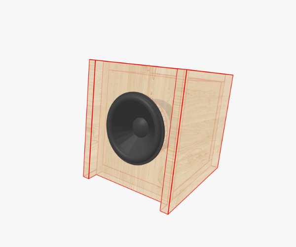
Steps to mount the speaker on a side of the box.
On the Objects inspector screen, I selected the Dayton TCP115-8 and clicked on the inclined face where I wanted it installed. Instantly, the driver appeared on the surface.
From here, positioning is simple: press and hold the driver icon until it transforms into a blue disk, then drag it into the center of the face. Release, and the driver locks into position.
The beauty of Speaker Box Lite is how it combines simulation and CAD-like manipulation without forcing you to learn a full 3D modeling suite.
Fine-Tuning the Front Look
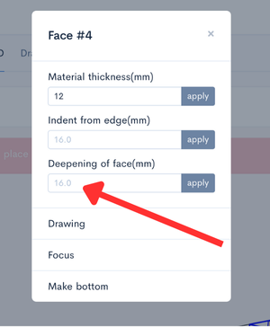
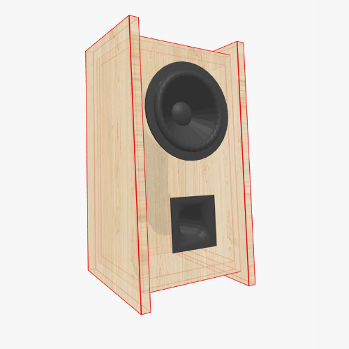
The final step to achieve the appearance I envisioned was to deepen the speaker’s mounting face. By applying a depth of 16 mm, the driver now sits recessed, giving the enclosure a professional look. The recessed mounting also creates a subtle effect: the left and right panels visually extend forward past the driver, while the driver itself feels integrated into the body rather than pasted on top.
Steps to deepen the box’s front side to achieve the result shown at the beginning.
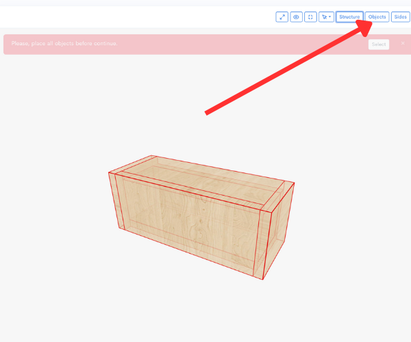
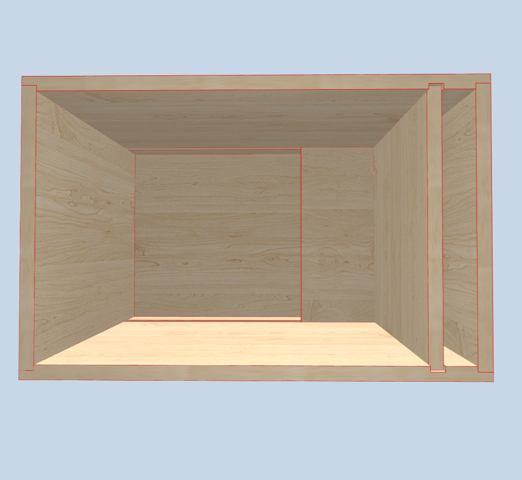
However, my first attempt recessed the wrong edges - top and bottom instead of left and right. To fix this, I explored the Box’s edges options. This screen highlights all edges in green, and you can change their connection types.
By adjusting the butt connections for the top, bottom, left, and right panels, I achieved the correct layout: the vertical sides extended forward, framing the driver beautifully.
Steps to change the sides butt connection.
This step demonstrates how enclosure design isn’t just about acoustics - it’s also about aesthetics. A box that sounds great but looks awkward won’t satisfy you on your desk.
Preparing the Blueprint
And that’s it - the enclosure is ready. To bring it into the workshop, all I needed was the Drawing screen. This feature generates a precise cutting map, complete with dimensions, material thickness, and joint types.
At this point, the project transitions from pixels to plywood. Cut the pieces, assemble them with glue and clamps, mount the driver, and you have a sealed bookshelf speaker perfectly tailored for your space.
Reflections on the Design
Designing this small sealed box highlighted the flexibility of Speaker Box Lite. I didn’t simply pick a number from a chart and build blindly. Instead, I:
Explored different enclosure volumes, compared graphs, and chose a balance between theory and practicality.
Modified the box shape to suit my listening environment.
Tuned the dimensions for space constraints without losing acoustic integrity.
Considered both the technical performance and the visual finish.
The result? A compact sealed enclosure that looks professional, fits neatly on my desk, and provides accurate, musical sound.
For anyone venturing into DIY speaker building, this process illustrates the synergy between physics and personal creativity. A sealed box may be simple, but within its simplicity lies endless room for refinement.
Conclusion
The sealed (closed) box remains one of the most versatile designs for DIY speaker projects. By combining its inherent acoustic benefits with the tools of Speaker Box Lite, you can create enclosures that not only perform well but also adapt to your personal space and style.
Whether you follow the exact steps here with the Dayton Audio TCP115-8 or choose your own driver, the process remains the same: simulate, experiment, refine, and then build.
And the best part? Every project you complete teaches you something new - not just about loudspeakers, but about the creative craft of transforming sound into something tangible.
👉 The project designed in this article is also available directly in Speaker Box Lite by the link here.
Can you explain the height, width, and length of the port?
Can you please explain the height, width, and length of the port? I have changed the height of the port to different numbers but the 3d rendering does not show any changes. I don't understand. When I go to view the parts, none of the dimension change. What part of the port does height and width signify?