Проектирование ВЧ-фильтров и кроссоверов в Speaker Box Lite
Разберитесь в принципах работы ВЧ-фильтров, влиянии ESR и DCR на звук, а также научитесь использовать инструменты симуляции в Speaker Box Lite для защиты твитеров.
Введение в фильтры ВЧ Полоса (High Pass) в аудио кроссоверах
Фильтр высоких частот (ВЧ-фильтр) - обычно называемый ВЧ Полоса (High Pass) - служит критически важным звеном в многополосных акустических системах. Его основная роль заключается в направлении высокочастотных сигналов на твитер при одновременном ослаблении низкочастотной энергии, для воспроизведения которой этот динамик не предназначен. Эта защита жизненно важна; низкие частоты несут в себе значительную мощность, которая может вызвать чрезмерный ход диффузора, что приведет к механической поломке или высокому уровню искажений. Speaker Box Lite упрощает эти сложные математические требования, позволяя энтузиастам DIY легко рассчитывать точные параметры фильтров и гарантировать, что их высокочастотные динамики работают безопасно и эффективно.
Основные преимущества реализации кроссовера ВЧ Полоса (High Pass)
Реализация кроссовера ВЧ Полоса (High Pass) дает ряд технических и акустических преимуществ, которые напрямую влияют на характеристики системы:
Улучшенная перегрузочная способность - Блокируя высокоэнергетические низкие частоты, твитер защищается от механических нагрузок и перегрева, что значительно повышает его надежность.
Снижение интермодуляционных искажений (IMD) - Когда динамик пытается воспроизвести частоты за пределами своего линейного диапазона, он создает искажения, окрашивающие звук. Фильтры ВЧ Полоса (High Pass) гарантируют, что твитер обрабатывает только те частоты, которые он может воспроизвести чисто.
Оптимизированная диаграмма направленности - Правильная фильтрация помогает поддерживать стабильную диаграмму направленности в точке раздела, предотвращая возникновение побочных лепестков и обеспечивая более широкую зону комфортного прослушивания.
Улучшенная звуковая сцена и четкость - Изоляция высокочастотного динамика позволяет ему передавать переходные процессы с большей точностью. Это приводит к более выраженной звуковой сцене и уровню прозрачности, которых невозможно достичь при использовании полнодиапазонного сигнала.
Влияние реальных паразитных параметров: ESR и DCR
В то время как математические модели обеспечивают надежную базу для проектирования кроссоверов, они часто подразумевают «идеальные» компоненты с нулевым внутренним сопротивлением. В реальности каждая физическая деталь привносит паразитные элементы, способные изменить работу фильтра. Двумя критически важными факторами являются эквивалентное последовательное сопротивление (ESR) в конденсаторах и сопротивление постоянному току (DCR) в катушках индуктивности. Игнорирование этих переменных приводит к расхождению между симуляцией и результатом физической сборки. Понимание этих неидеальных характеристик необходимо для того, чтобы ваш кроссовер работал именно так, как планировалось, после того как он сойдет с экрана и будет собран в корпусе акустической системы.
Важность ESR для последовательных конденсаторов
Эквивалентное последовательное сопротивление (ESR) представляет собой внутренние омические потери в конденсаторе. В кроссовере ВЧ Полоса (High Pass) конденсатор включен непосредственно в последовательную цепь сигнала, что делает его ESR критическим фактором для характеристик. Высокие значения ESR ухудшают добротность фильтра, приводя к более «мягкому» спаду и менее точному управлению частотой, чем предполагает математический идеал.
Помимо влияния на амплитудно-частотную характеристику, ESR действует как резистор, включенный последовательно с динамиком, вызывая нежелательное затухание сигнала. Это сопротивление также преобразует электрическую энергию в тепло - важный фактор в мощных аудиосистемах, где термическая стабильность необходима для поддержания стабильного качества звука и долговечности компонентов.
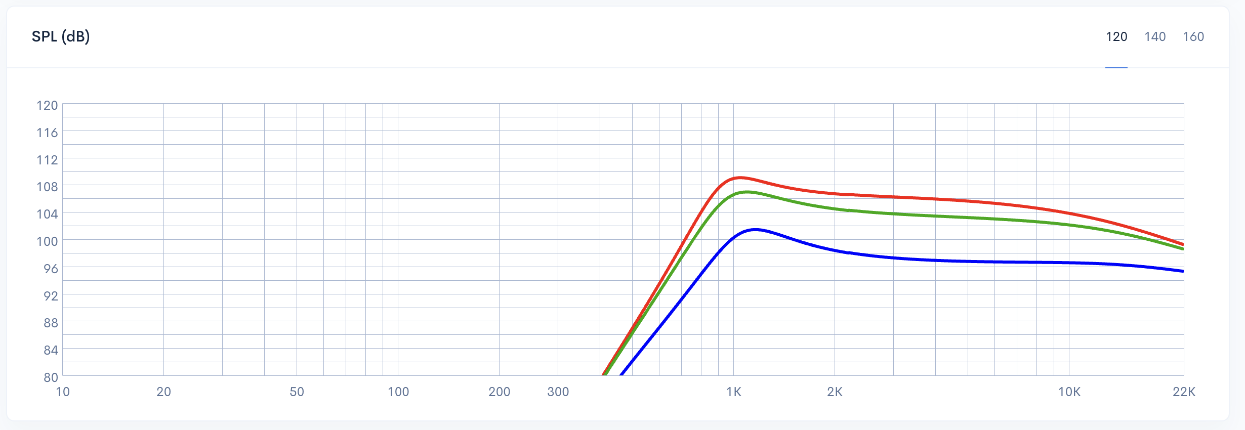
Влияние значений ESR конденсатора на график SPL - 0.2 Ом (красный), 2 Ом (зеленый) и 10 Ом (синий)
Роль DCR в параллельных катушках индуктивности
Сопротивление постоянному току (DCR) - это внутреннее сопротивление медной обмотки катушки индуктивности. В фильтрах ВЧ Полоса (High Pass) катушка индуктивности выступает в роли шунтирующего компонента на землю. Её DCR напрямую влияет на демпфирование фильтра и профиль Импеданс (Impedance), который видит усилитель. Низкое значение DCR идеально для поддержания расчетной крутизны спада, хотя это требует использования более толстого провода и увеличения габаритов компонентов. Высокие значения DCR вносят потери, которые могут «смягчить» отклик фильтра или - если они достаточно высоки - фактически отключить шунтирующую ветвь из цепи. Это делает баланс между DCR и физическим размером критически важным для точности кроссовера.
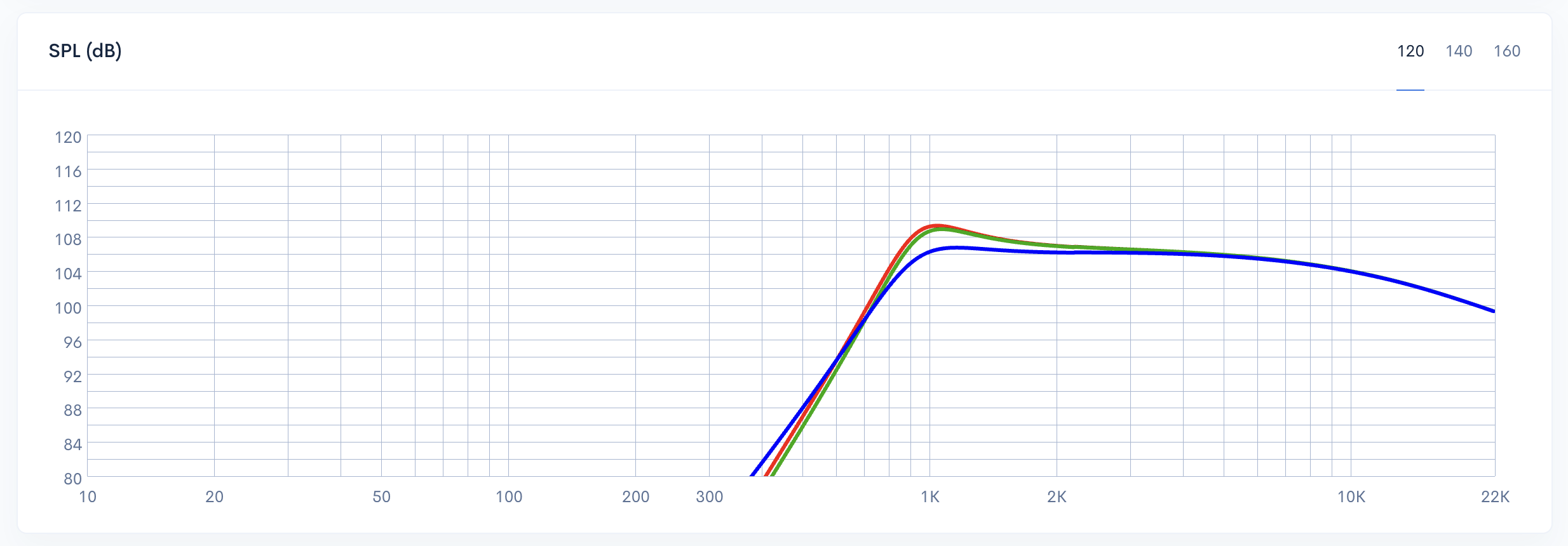
Влияние DCR параллельной катушки индуктивности на SPL-отклик кроссовера ВЧ Полоса (High Pass) - 0.2 Ом (красный), 2 Ом (зеленый) и 1000 Ом (синий)
Справочные данные: средние значения ESR и DCR для компонентов
Для достижения высокой точности моделирования в Speaker Box Lite необходимо вводить реалистичные значения паразитных параметров. Используйте следующие справочные данные по ESR и DCR в качестве базовых значений, если спецификации конкретных производителей недоступны:
Конденсаторы (сравнение ESR):
Электролитические: Часто используются в шунтирующих цепях большой емкости для снижения стоимости. Они обладают более высоким эквивалентным последовательным сопротивлением (ESR), которое обычно составляет от 0,5 до 2,0 Ом.
Полипропиленовые или пленочные: Золотой стандарт для Hi-Fi аудио, обеспечивающий превосходную стабильность и чрезвычайно низкое ESR - часто менее 0,1 Ом.
Керамические (MLCC): Иногда встречаются в цепях компенсации Импеданс (Impedance) или байпасных цепях. Они обеспечивают очень низкие значения ESR - обычно от 0,01 до 0,2 Ом - хотя они реже используются в основных сигнальных трактах НЧ из-за чувствительности к напряжению.
Катушки индуктивности (сравнение DCR):
Воздушный сердечник: Ценятся за отсутствие магнитного насыщения. Однако для достижения высоких значений индуктивности им требуется больше провода, что приводит к более высокому сопротивлению постоянному току (DCR).
Ферритовый или стальной сердечник: Использование магнитного сердечника позволяет получить высокую индуктивность при меньшем количестве витков провода. Это приводит к значительно более низкому DCR - сохраняя чувствительность системы - хотя проектировщики должны учитывать риск насыщения сердечника при высоких уровнях мощности.
Пошаговое руководство: использование инструмента кроссовера ВЧ Полоса (High Pass) в Speaker Box Lite
Чтобы начать проектирование кроссовера, перейдите на вкладку Сеть (Network) в вашем проекте Speaker Box Lite. Сначала включите опцию Внешняя сеть (External network), чтобы активировать движок симуляции схем. В разделе фильтров вы найдете предустановленный элемент ВЧ Полоса (High Pass). Пользователи мобильного приложения могут нажать на элемент для настройки, в то время как пользователям WEB-версии следует нажать на кнопку «...» рядом с ним. Это откроет экран параметров ВЧ, где вы сможете указать Импеданс (Impedance) динамика, Частоту Среза (Frequency Cutoff) и выбрать предпочтительную модель аппроксимации.
Выбор порядка фильтра и крутизны спада
В Speaker Box Lite вы можете выбрать порядок фильтра от 1-го до 6-го, чтобы определить крутизну спада. Повышение порядка увеличивает сложность кроссоверной Сеть (Network) - каждый дополнительный шаг требует наличия еще одного пассивного компонента (катушки индуктивности или конденсатора). Полученная крутизна спада составляет:
1-й порядок: 6 дБ/октава (1 компонент)
2-й порядок: 12 дБ/октава (2 компонента)
3-й порядок: 18 дБ/октава (3 компонента)
4-й порядок: 24 дБ/октава (4 компонента)
5-й порядок: 30 дБ/октава (5 компонентов)
6-й порядок: 36 дБ/октава (6 компонентов)
Хотя более крутые спады обеспечивают лучшую изоляцию динамиков, они требуют более точной настройки и увеличивают количество физических компонентов в системе.
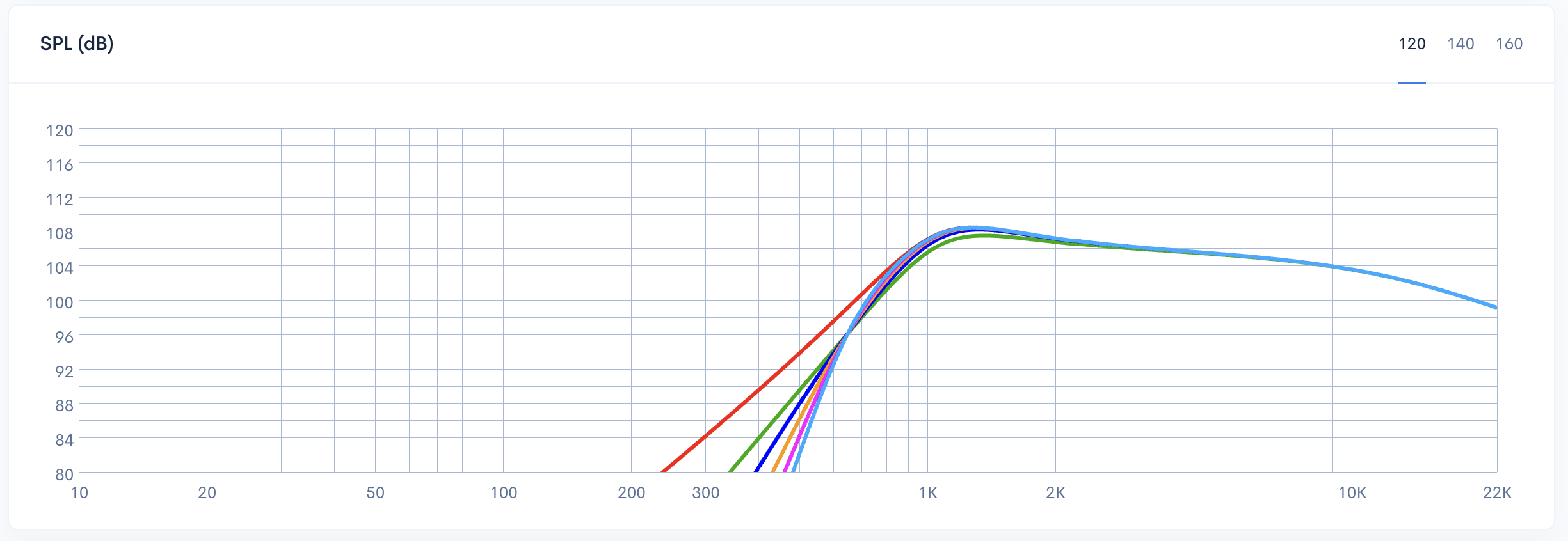
Сравнение крутизны спада фильтров ВЧ Полоса (High Pass) с 1-го по 5-й порядок
Поля ввода: Импеданс (Impedance) и Частота Среза (Frequency Cutoff)
Настройка начинается с двух основных полей ввода: Импеданс (Impedance) (динамика) и Частота Среза (Frequency Cutoff). Для обеспечения точности используйте фактический измеренный Импеданс (Impedance) динамика на частоте кроссовера вместо его номинального значения 4 или 8 Ом. Это критически важно, так как реальный Импеданс (Impedance) динамика колеблется во всем частотном спектре. Частота Среза (Frequency Cutoff) отмечает точку, в которой фильтр начинает ослаблять низкие частоты. Точная калибровка здесь необходима для плавного перехода между динамиками и поддержания сбалансированной, цельной частотной характеристики во всей аудиосистеме.
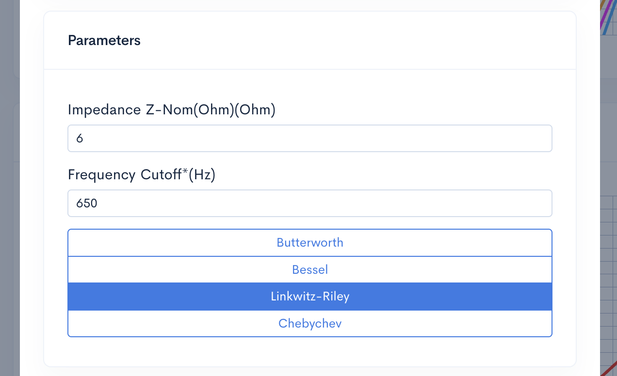
Конфигурация ВЧ Полоса (High Pass) - поля ввода Импеданс (Impedance) и Частота Среза (Frequency Cutoff)
Доступные аппроксимации фильтров и их характеристики
Выбор правильной математической аппроксимации в Speaker Box Lite имеет решающее значение для определения звукового характера и поведения вашего высокочастотного динамика в зоне перехода. Каждая аппроксимация предлагает уникальный компромисс между амплитудно-частотной характеристикой и точностью фазы:
Баттерворт (Butterworth): Часто называемый фильтром с «максимально плоской» характеристикой, он обеспечивает максимально ровную АЧХ в полосе пропускания. Это универсальный выбор для фильтрации ВЧ Полоса (High Pass), хотя он и демонстрирует умеренный «звон» во временной области.
Бессель (Bessel): Оптимизирован для наилучшего группового времени задержки и Лин. Фаза (Linear Phase) характеристики. Хотя он имеет самый плавный начальный спад, аудиофилы предпочитают его за превосходное воспроизведение переходных процессов и минимальные фазовые искажения.
Линквитз-Рилей (Linkwitz-Riley): Стандарт для кроссоверов высокого порядка, особенно 24 дБ/октава. В отличие от других, он имеет уровень -6 дБ на Частота Среза (Frequency Cutoff), обеспечивая плоскую суммарную амплитудную характеристику при использовании с соответствующим фильтром НЧ Полоса (Low Pass).
Чебышев (Chebychev): Эта аппроксимация обеспечивает самый крутой спад для защиты чувствительных динамиков. Однако это достигается за счет пульсаций в полосе пропускания, что делает его подходящим для задач, где быстрое затухание важнее абсолютной равномерности.
Доступные аппроксимации фильтров 2-го порядка: Баттерворт (Butterworth), Бессель (Bessel), Линквитз-Рилей (Linkwitz-Riley) и Чебышев (Chebychev)
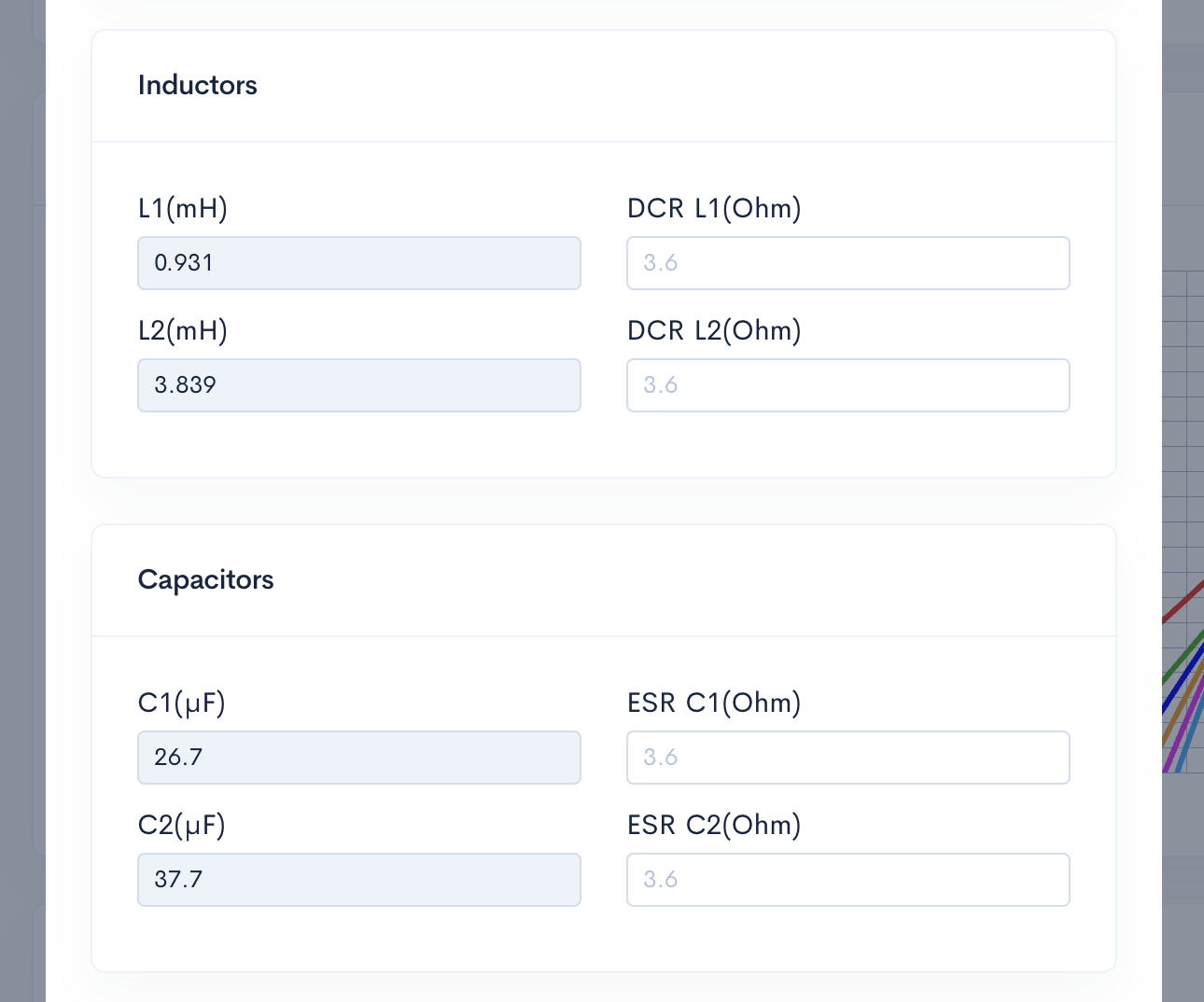
Рассчитанные значения компонентов L и C
После указания Импеданс (Impedance) динамика и желаемой Частота Среза (Frequency Cutoff), Speaker Box Lite автоматически рассчитывает теоретические значения L (индуктивности) и C (емкости) для выбранной аппроксимации. Количество компонентов - таких как L1, C1 или L2 - динамически изменяется в зависимости от выбранного порядка фильтра. Для высокоточного моделирования интерфейс включает специальные поля для паразитного сопротивления: ESR для каждого конденсатора и DCR для каждой катушки индуктивности. По умолчанию они установлены в 0 Ом и 0.2 Ом соответственно, что позволяет уточнить модель для достижения реалистичной точности.
Точность моделирования: простые и сложные модели
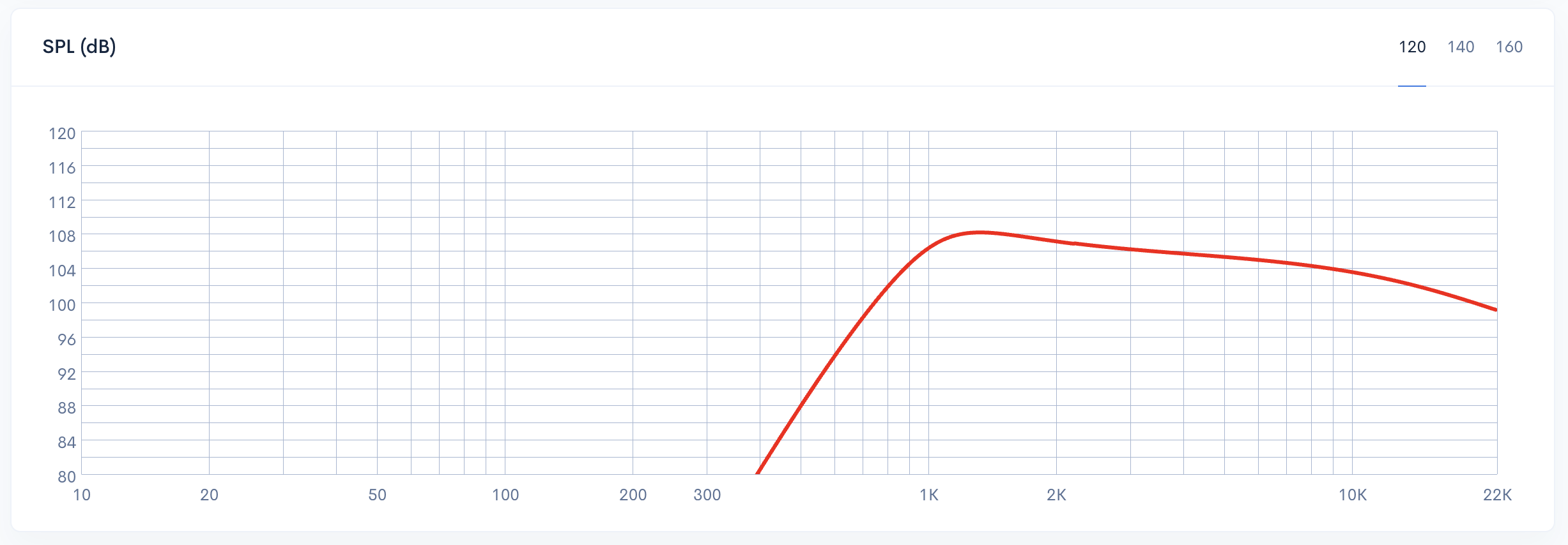
В Speaker Box Lite выбор между простыми и сложными моделями определяет уровень детализации вашего моделирования. Простые модели оптимизированы для быстрого прототипирования: они используют идеальные передаточные функции и выходное SPL для создания быстрого - чернового - наброска поведения фильтра. Напротив, сложные модели обеспечивают точность лабораторного уровня, рассчитывая реальные переменные. Они учитывают полную кривую Импеданс (Impedance) динамика и паразитные параметры, такие как ESR и DCR. За счет учета этих физических факторов сложная модель гарантирует, что смоделированный отклик будет соответствовать фактическим измеренным характеристикам вашего готового кроссовера.
График АЧХ (SPL) в простом режиме - идеальная передаточная функция без влияния ESR и DCR
Расширенное управление: Реализация компонентов L и C через Элементы вручную (Custom elements)
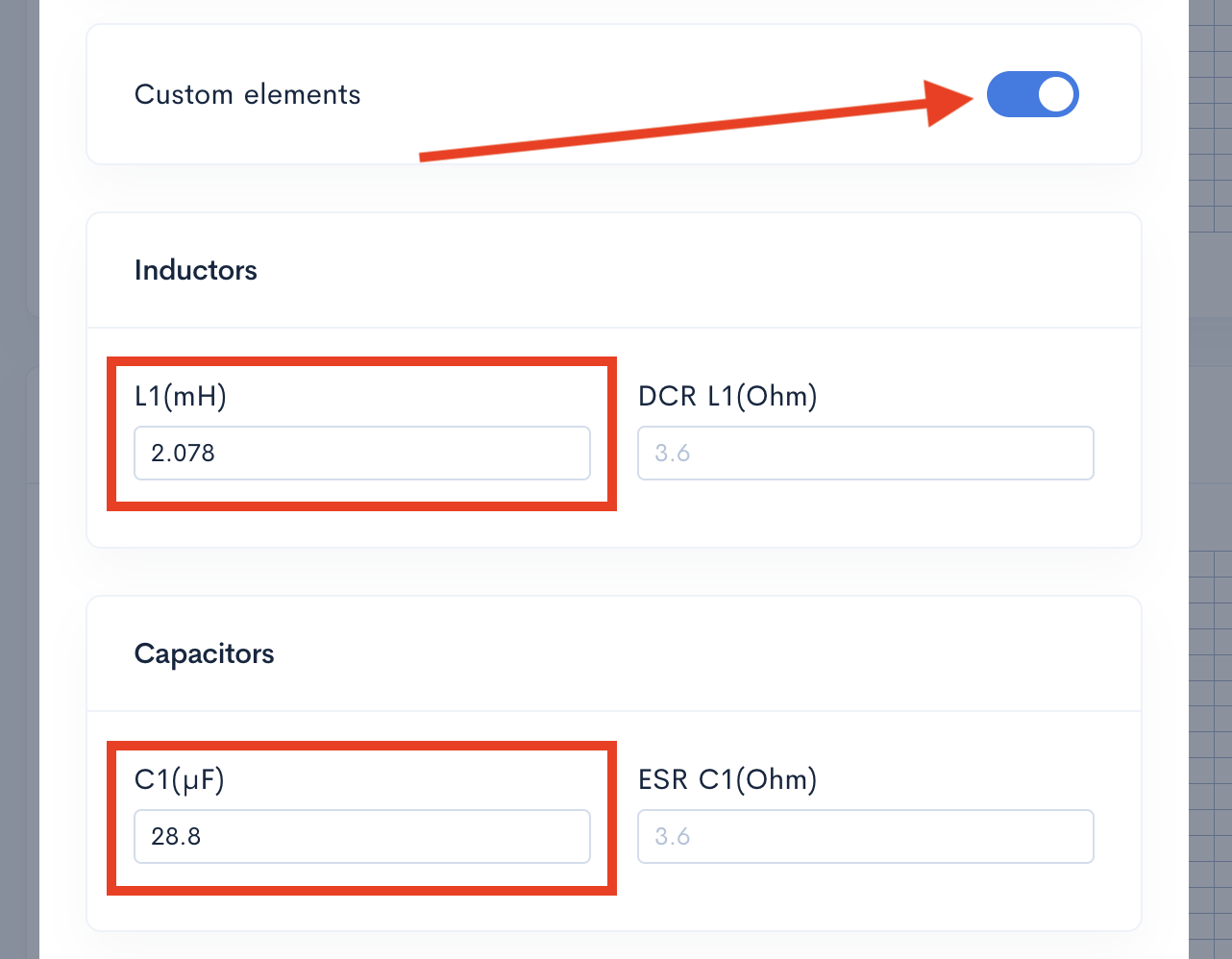
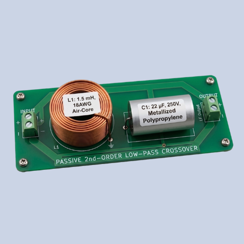
Хотя Speaker Box Lite предлагает точные теоретические аппроксимации, проектирование в реальном мире часто требует большей гибкости. Активируя переключатель Элементы вручную (Custom elements), вы получаете полный ручной контроль над фильтром Сеть (Network). Этот режим позволяет переопределять расчетные значения и напрямую вводить конкретные величины индуктивности (L) и емкости (C). Это особенно полезно при адаптации вашего проекта под стандартные компоненты, которые могут отличаться от идеальных расчетов. Будь то тонкая настройка отклика или использование имеющегося в наличии инвентаря, режим Элементы вручную (Custom elements) обеспечивает универсальность, необходимую для оптимизации профессионального уровня.
Режим Элементы вручную (Custom elements) для ручного ввода параметров L и C
Заключение: Интеграция фильтров ВЧ Полоса (High Pass) для превосходного звука
Интеграция фильтра ВЧ Полоса (High Pass) - это не просто математическое упражнение, это основа для защиты ваших динамиков и достижения чистоты звучания. Сочетая теоретические принципы аппроксимации с мощностью моделирования Speaker Box Lite, вы можете совершенствовать свои проекты с полной уверенностью. Мы рекомендуем итеративный подход: начните с простых моделей для построения целевой АЧХ, а затем переходите к сложным симуляциям, чтобы учесть влияние реальных параметров ESR и DCR. Такой рабочий процесс гарантирует, что ваша финальная сборка обеспечит идеальный баланс термической стабильности и высокого качества звучания.
Can you explain the height, width, and length of the port?
Can you please explain the height, width, and length of the port? I have changed the height of the port to different numbers but the 3d rendering does not show any changes. I don't understand. When I go to view the parts, none of the dimension change. What part of the port does height and width signify?