LF Crossover Design: Optimizing Filters in Speaker Box Lite

A technical guide to low-frequency filters, covering component parasitics like ESR and DCR, and how to implement precision crossovers in Speaker Box Lite.

Introduction to Low-Frequency (LF) Filters in Audio Crossovers

In any multi-way speaker system, the low-frequency (LF) filter - or low-pass filter - serves as a foundational tool for frequency management. Its primary function is to direct low-end energy toward the woofer while progressively attenuating higher frequencies that the driver cannot accurately reproduce. By rolling off the high-frequency spectrum, the filter prevents cone breakup - a common source of harsh distortion - and mitigates phase interference with the tweeter. This ensures that each driver operates within its optimal bandwidth, resulting in a cohesive, balanced, and technically accurate acoustic output.

Primary Benefits of LF Crossover Implementation

Implementing an LF crossover provides several critical technical advantages that go beyond simple frequency management. By carefully defining the operational window of the driver, you achieve the following benefits:

  1. Enhanced Power Handling: By filtering out high-frequency energy that the woofer cannot efficiently convert to sound, the filter reduces thermal stress on the voice coil. This allows the driver to operate more safely at higher output levels within its intended range.
  2. Reduction of Intermodulation Distortion (IMD): When a woofer attempts to reproduce high frequencies while simultaneously moving for deep bass, intermodulation occurs. Removing high-frequency content minimizes this effect, resulting in significantly cleaner midrange reproduction.
  3. Optimized Directivity Control: As drivers approach higher frequencies, their dispersion narrows - a phenomenon known as beaming. An LF filter ensures the driver is attenuated before it becomes too directional, facilitating a smoother polar response transition to the tweeter.
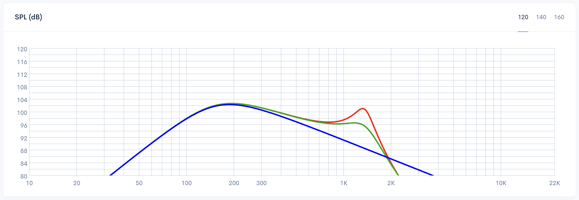
  4. Cone Breakup Mitigation: Filtering prevents the excitation of high-frequency resonances within the driver's cone material, eliminating harsh peaks and artifacts in the acoustic response.

The Impact of Real-World Parasitics: ESR and DCR

In theoretical crossover design, inductors and capacitors are often treated as ideal components with zero internal resistance. However, physical reality introduces parasitics that can significantly alter a filter's performance. The most critical factor is series resistance - specifically Direct Current Resistance (DCR) in inductors and Equivalent Series Resistance (ESR) in capacitors.

These parasitic elements are not just minor nuisances; they directly modify the damping and Q-factor of the circuit. High series resistance can cause a rounding of the filter knee or unintended attenuation, causing the actual acoustic slope to deviate from the mathematical model.

The Importance of ESR for Shunt Capacitors

The Equivalent Series Resistance (ESR) of a shunt capacitor is a critical factor in defining filter precision. In a low-pass crossover, the shunt capacitor acts to bypass high-frequency energy away from the driver. If the ESR is too high, it limits the capacitor’s ability to shunt these frequencies, effectively reducing the depth of the filter notch and dampening the circuit response.

High ESR can lead to a functional "disconnecting" of the capacitor, which degrades the filter order and leads to a less effective high-frequency roll-off. Beyond frequency response issues, excessive ESR contributes to unwanted heat generation, potentially affecting component longevity and system efficiency.


2nd-order low-pass filter response with shunt capacitor ESR variations: 0.2 Ohms (red), 2 Ohms (green), and 100 Ohms (blue)

The Role of DCR in Series Inductances

While capacitors shunt high-frequency energy, series inductors act as the primary gatekeeper for low-pass signals. Every inductor possesses Direct Current Resistance (DCR) - the inherent resistance of the wire itself. Because this component sits directly in series with the driver, its DCR adds to the voice coil resistance, effectively increasing the total impedance seen by the amplifier. This added resistance causes a direct loss in voltage sensitivity (SPL), as power is dissipated within the coil. Furthermore, DCR significantly impacts the system's Qts by raising the electrical Q (Qes), which can lead to a less controlled bass response and reduced cone damping.


2nd order LF filter response comparison with varying inductor DCR values - 0.2 Ohms (red), 2 Ohms (green), and 10 Ohms (blue)

Reference Data: Average ESR and DCR Values for Components

When designing an LF crossover in Speaker Box Lite, selecting the appropriate component type is critical as their parasitic values directly influence the filter's final transfer function. Below are the industry-standard reference values for commonly used crossover components:

Capacitors (ESR Comparison):

  1. Electrolytic: Often utilized in high-capacity shunt circuits for cost efficiency. These exhibit higher Equivalent Series Resistance, generally ranging from 0.5 to 2.0 Ohms.
  2. Polypropylene or Film: The gold standard for high-fidelity audio, offering superior stability and extremely low ESR - often less than 0.1 Ohms.
  3. Ceramic (MLCC): Occasionally found in impedance compensation or bypass circuits, these offer very low ESR values - typically between 0.01 and 0.2 Ohms - though they are less common in primary LF signal paths due to voltage sensitivity.

Inductors (DCR Comparison):

  1. Air Core: Prized for their lack of magnetic saturation. However, they require more wire to reach high inductance values, resulting in a higher Direct Current Resistance (DCR).
  2. Ferrite or Iron Core: Utilizing a magnetic core allows for high inductance with fewer wire turns. This results in much lower DCR - preserving system sensitivity - though designers must account for the risk of core saturation at high power levels.

Step-by-Step: Using the LF Crossover Tool in Speaker Box Lite

To begin designing your crossover, navigate to the Network tab within your Speaker Box Lite project. First, locate and enable the External network option to activate the circuit simulation engine. Under the Filter section, you will find a pre-added Low Pass item. To access the configuration settings, mobile app users can simply tap the item directly, while WEB version users should click the ... button adjacent to it. This action opens the LF parameters screen, where you can define the driver's impedance, target cutoff frequency, and select your preferred alignment model.

Selecting the Filter Order and Roll-off Slope

Within Speaker Box Lite, you can select a filter order from 1st to 6th to define the attenuation rate. Increasing the order directly impacts the complexity of the crossover network - each additional order requires an extra passive component (either an inductor or capacitor). The resulting roll-off slopes are:

  1. 1st Order: 6 dB/octave (1 component)
  2. 2nd Order: 12 dB/octave (2 components)
  3. 3rd Order: 18 dB/octave (3 components)
  4. 4th Order: 24 dB/octave (4 components)
  5. 5th Order: 30 dB/octave (5 components)
  6. 6th Order: 36 dB/octave (6 components)

While steeper slopes provide better driver isolation, they demand more precise tuning and increase the physical part count of your system.


SPL frequency response comparison of 1st-5th order low-pass filter roll-off slopes in Simple network mode without ESR and DCR influence
1st-order low-pass crossover schematic - 6 dB per octave roll-off
2nd-order low-pass crossover schematic with 12 dB/octave roll-off
3rd-order low-pass crossover schematic with 18 dB/octave roll-off
4th order low-pass filter schematic - 24 dB/octave roll-off
5th-order low-pass filter schematic with 30 dB/octave roll-off
6th-order low-pass filter schematic for 36 dB/octave attenuation

Input Fields: Impedance and Cutoff Frequency

The configuration begins with two fundamental parameters: Impedance (driver) and Frequency Cutoff. To achieve precise results, the impedance value should reflect the driver's actual measured impedance at the specific crossover point rather than its nominal rating, such as 4 or 8 ohms. This is because real-world driver impedance varies significantly across the frequency spectrum. The Frequency Cutoff defines the transition point where the filter starts to attenuate higher frequencies. Setting this accurately is essential for managing the hand-off between drivers and maintaining a cohesive frequency response throughout the audio system.


Driver Impedance and Cutoff Frequency configuration fields in the Speaker Box Lite LF crossover settings

Available Filter Alignments and Their Characteristics

Choosing the correct mathematical alignment in Speaker Box Lite is essential for defining the sonic character and transition behavior of your audio system. Each alignment offers a unique trade-off between frequency magnitude and phase accuracy:

  1. Butterworth: Often called the 'maximally flat' filter, it provides the flattest possible response in the passband. It is a versatile choice for general audio work, though it exhibits moderate ringing in the time domain.
  2. Bessel: Optimized for the best group delay and linear phase response. While it has the softest initial roll-off, it is preferred by audiophiles for its superior transient reproduction and minimal phase distortion.
  3. Linkwitz-Riley: The standard for high-order crossovers, specifically 24dB/octave. Unlike others, it is -6dB at the cutoff frequency, ensuring a flat summed magnitude response when paired with a matching high-pass filter.
  4. Chebychev: This alignment provides the steepest roll-off for a given order. However, this comes at the cost of ripple within the passband, making it suitable for applications where rapid attenuation is prioritized over absolute flatness.


Available 2nd order Butterworth, Bessel, Linkwitz-Riley, and Chebychev filter alignments
Available 3rd order Butterworth, and Bessel filter alignments
Available 4th order Butterworth, Bessel, Linkwitz-Riley, Legendre and Gaussian filter alignments
Available 5th order Butterworth filter alignment
Available 6th order Linkwitz-Riley filter alignment

Calculated L and C Component Values

Once you define the driver Impedance and desired Cutoff Frequency, Speaker Box Lite automatically calculates the theoretical L (inductance) and C (capacitance) values required to meet your selected alignment. The specific number of components - such as L1, C1, or L2 - dynamically scales based on the chosen filter order. To achieve a high-precision simulation, the interface provides dedicated fields for parasitic resistance: ESR next to each capacitor and DCR next to each inductor. By default, these are set to 0.2 Ohms and 0 Ohms, respectively, allowing you to refine the model for real-world accuracy.


Calculated L and C component values for a 2nd-order LF filter

Simulation Accuracy: Simple vs. Complex Models

In Speaker Box Lite, choosing between Simple and Complex models determines the depth of your simulation. Simple models are designed for rapid prototyping, focusing on the ideal transfer function and SPL output to give you a quick - draft - of the filter's behavior. In contrast, Complex models provide laboratory-grade accuracy by accounting for real-world variables. These include the driver's full impedance curve and parasitic elements like ESR and DCR. By incorporating these physical constraints, the Complex model ensures that the simulated response aligns perfectly with the measured performance of your finished crossover.


SPL response graph in Simple mode - ideal transfer function without ESR and DCR influence
SPL response graph in Complex mode showing the influence of ESR and DCR parasitic resistance

Advanced Control: Implementing Custom L and C Elements

While Speaker Box Lite provides precise theoretical alignments, real-world engineering often requires flexibility. By enabling the "Custom elements" switcher, you gain full manual control over the filter network. This mode allows you to override the calculated values and type in specific Inductance (L) and Capacitance (C) values directly. This is particularly useful when you need to adapt your design to "off-the-shelf" components that may differ slightly from ideal calculations. Whether you are fine-tuning the response or utilizing parts already in your inventory, Custom mode provides the necessary versatility for professional-grade optimization.


Custom elements mode for manual entry of L and C parameters

Conclusion: Integrating LF Filters for Superior Sound

Integrating a low-frequency filter is more than just a theoretical calculation; it requires a balance between mathematical precision and real-world variables. By selecting the optimal filter alignment - whether it be Butterworth for flatness or Linkwitz-Riley for phase coherence - and accounting for parasitic elements like ESR and DCR, you ensure that your simulation matches the physical prototype. Speaker Box Lite provides the specialized tools to bridge this gap. Mastering these parameters transforms a basic crossover into a high-performance system, resulting in predictable, professional sound quality and long-term reliability for any audio project.


Bagikan: